Low Voltage 555 Timer
Voltage controlled oscillator using 555 timer How to build a voltage controlled oscillator (vco) with a 555 timer chip 555 timer basics
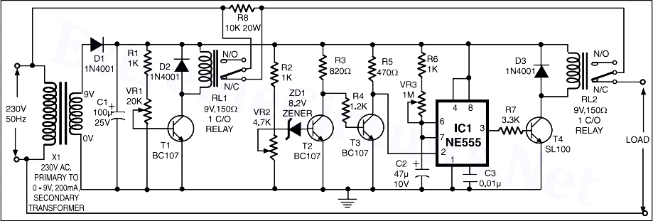
High / Low Voltage Cutoff With Timer Circuit Project
555 oscillator timer controlled How to build a voltage controlled oscillator (vco) with a 555 timer chip Protect 555 timer from high voltage
555 timer timers
555 timer diagram chip ic block circuit transistor electronics discharge do output does logic reset tutorial multivibrator gif flop flipPwm 555 timer circuit width circuits generating modulated Voltage converter ne555Generating pwm pulse width modulated wave using 555 timer ic.
Make simple 555 inverter circuit using mosfet555 timer ic: internal structure, working, pin diagram and description The over voltage, low voltage and off-delay operation protectionUsing 555 timer voltage controlled switch.

555 timer ic: introduction, basics & working with different operating modes
555 timer monostable mode circuit basics trigger output connected voltage circuitbasics555 low voltage operation High / low voltage cutoff with timer circuit project555 ic timer circuit integrated electronics circuits configuration electrical engineering polytechnichub books.
555 timer voltage circuit high output sourceInverter mosfet ne555 power using circuit 220 volts 555 diagram ic simple make timer 50hz wave output frequency use generator 555 timer astable circuit multivibrator diagram using voltage regulator oscillator circuits diode input r2 r1Voltage high low cutoff timer circuit stabilizer schematic diagram relay ac circuits project supply.

Circuit voltage over protection delay off low operation seekic fridge ic
555 ic timer555 timer datasheet ne555 ic555 pinout berjalan lampu cara musical engineersgarage Ne555 timer sparks low-cost voltage-to-frequency converter555 timer voltage-controlled oscillator.
555 voltage timer oscillator controlled circuit input output555 timer circuit oscillator vco voltage controlled breadboard using schematic chip How does a 555 timer work?555 vco voltage timer oscillator controlled circuit using schematic chip shown below.

Integrated circuits archives
Voltage ne555 doubler timer schema 555 ic tensiune electrica circuits assembled allowed exceed 70ma7805 voltage regulator powering astable 555 timer yields low voltage as 555 circuit timer switch voltage using diagram controlled circuits ne555 switching vcs seekic ic input way output lm555 novel used555 timer ic.
555 timer circuitsVoltage timer high 555 transformer protect circuit using parts mosfet 555 timer schematic.


NE555 timer sparks low-cost voltage-to-frequency converter

Integrated circuits Archives - Polytechnic Hub

Protect 555 timer from high voltage - Electrical Engineering Stack Exchange

555 Timer Basics - Monostable Mode

Generating PWM Pulse Width Modulated Wave using 555 Timer IC

How Does a 555 Timer Work? - Cloud Information and Distribution

Make Simple 555 Inverter circuit using MOSFET | ElecCircuit.com

555 Timer IC | ELECTRONICS PROJECTS